This guide provides step-by-step instructions for assembling the Smart Motor V3 with 3D printed parts.
Table of Contents
Introduction
The Smart Motor V3 uses a custom Smart Motor board with ESP32C3. In the following steps you will find instructions on how to order the boards from Seeed Studio. You will also find the files to 3D print and parts you will need to order to build your own Smart Motors. Send us and email if you build one at milan.dahal@tufts.edu.
Note: PCB fabrication takes approximately one month from ordering to delivery.
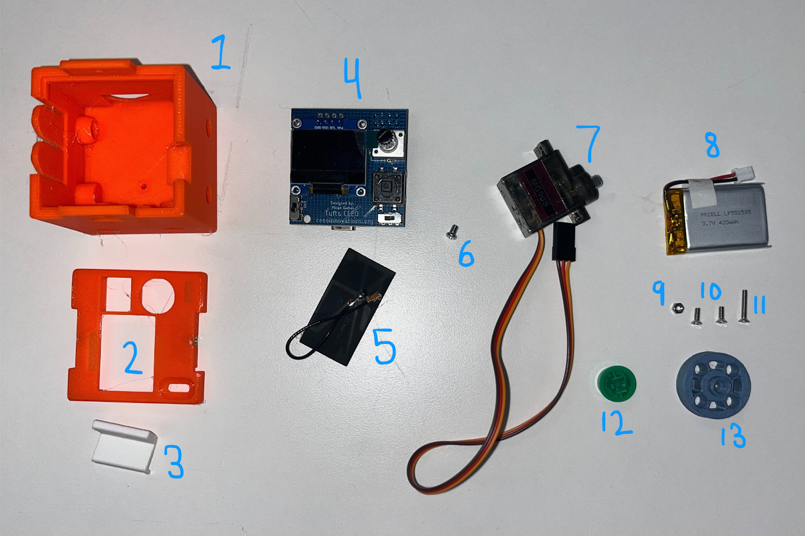
Preparing the parts
Smart Motors V3 has a printed circuit board (PCB), a servo motor and a battery inside the 3D printed case. The case is held together with bolts and threaded nuts. Below are the instructions on where to find all the materials.Ordering Smart Motors PCBs.
In order to order the PCBs from Seeed Studio:
- Go to Seeed Studio Fusion PCB (sign up/login required)
- Upload the gerber files: GerberFiles.zip
- Upload the instructions: Instructions.zip
- Upload the bill of materials: BOM.xlsx
3D printing Smart Motor parts.
Print the following STL files. Make sure you print the Top with PLA filament as we need to put heated inserts.


Ordering parts and materials.
Order the following components to complete the assembly.| Item | Quantity | Link |
|---|---|---|
| Servo motor | 1 | Amazon Link |
| LiPo Battery | 1 | Adafruit Link |
| PLA filament | As needed | - |
| M2 screw, 10 mm | 1 | McMaster Link |
| M2 screw, 4 mm | 2 | McMaster Link |
| M2 nut | 1 | McMaster Link |
| M2 threaded inserts | 2 | Amazon Link |
| Button cap | 1 | Amazon Link |
| Grove light sensor | 1 | Seeed Studio Link |
| I²C OLED display (if Seeedstudio cannot find the display) | 1 | Amazon Link |
Note: Seeedstudio may email you saying they cannot find the OLED screens. You should ask them to try to find the part OLED with part number ZJY096I0400BG01. If they cannot find the OLED, you will need to oder the OLED screens (link above) and solder them on your own (instructions below).
Assembly Instructions
Note: You can follow along with the video tutorial for visual assembly guidance. Please note, the instructions in the video are for assembling Smart Motor without a battery.
Step 1: Prepare the Electronics
-
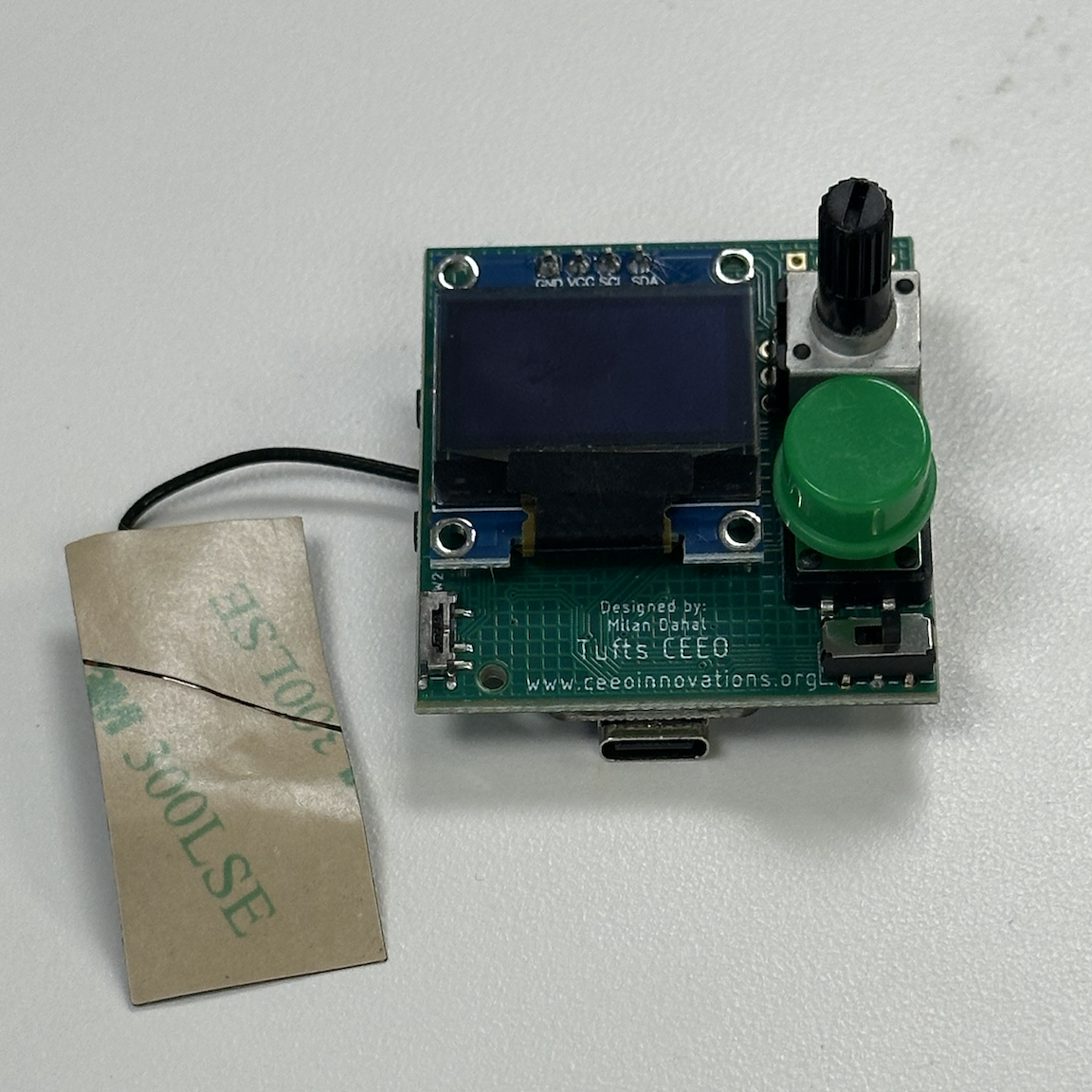
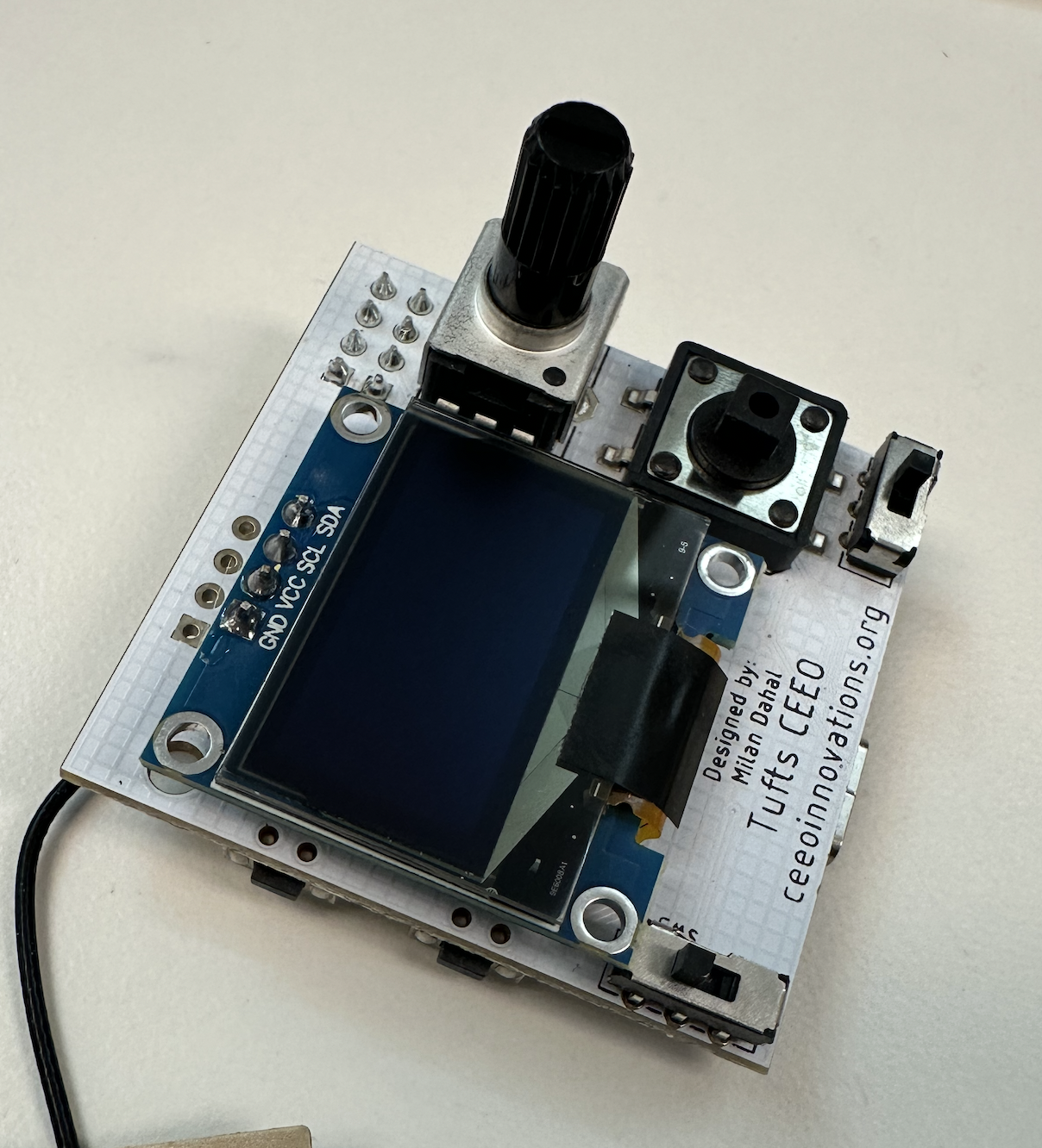
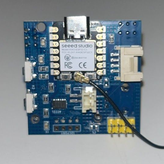
Solder the OLED screen to the Smart Motor board. Solder them in the second row of headers as shown in the image. (Skip this step if your board already has OLED screen.)
-
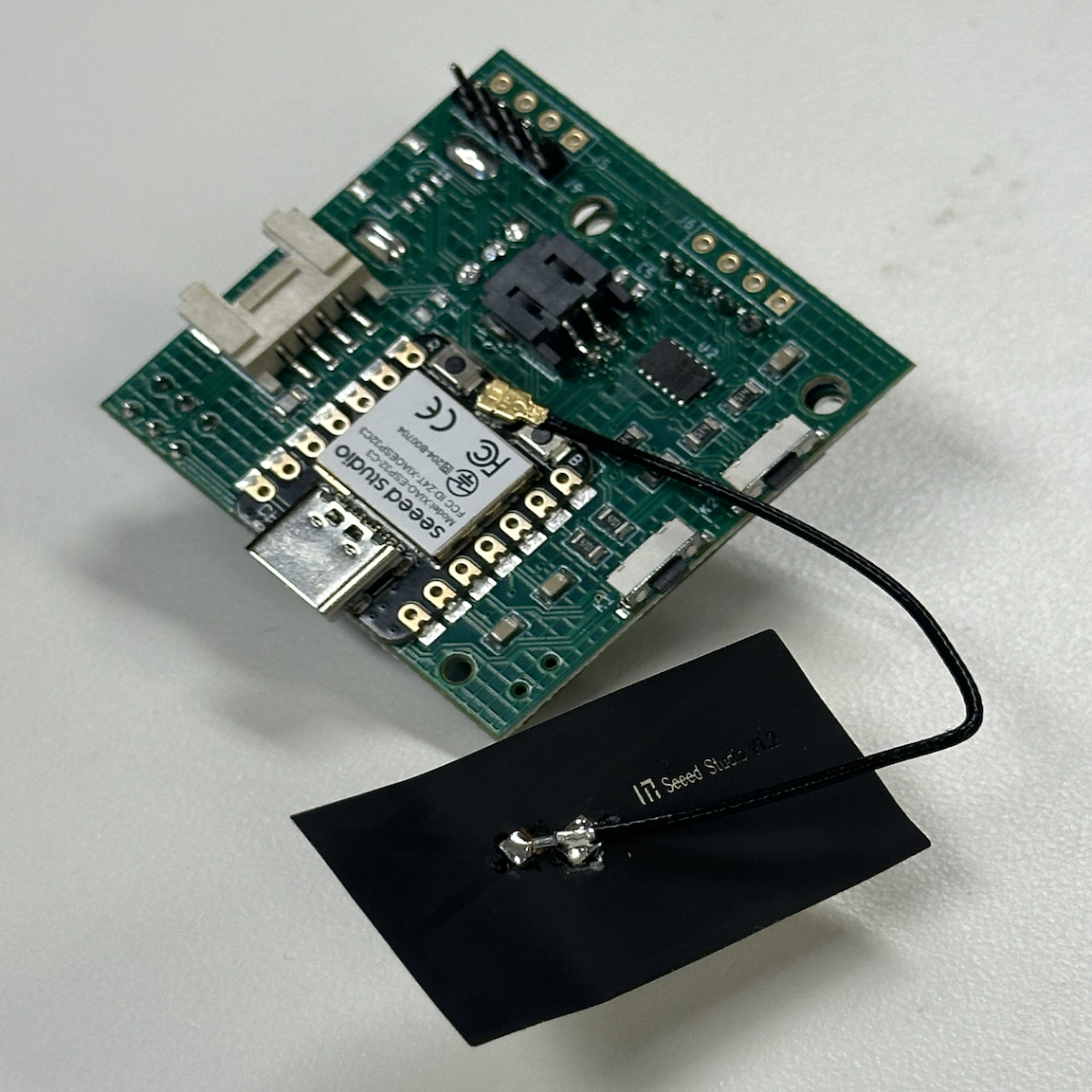
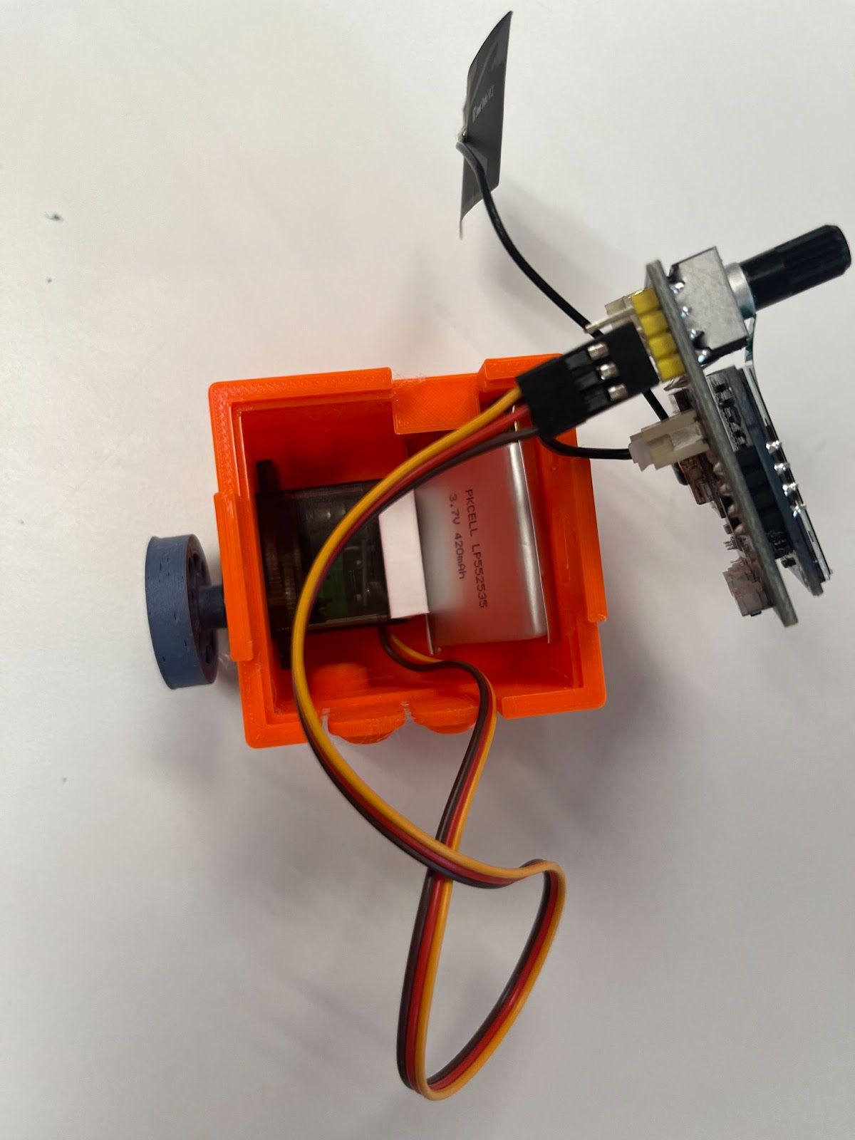
Attach the antenna to the Smart Motor board.
- Angle the side opposite to the wire more downward to help with insertion
- Press firmly until it snaps into place
-
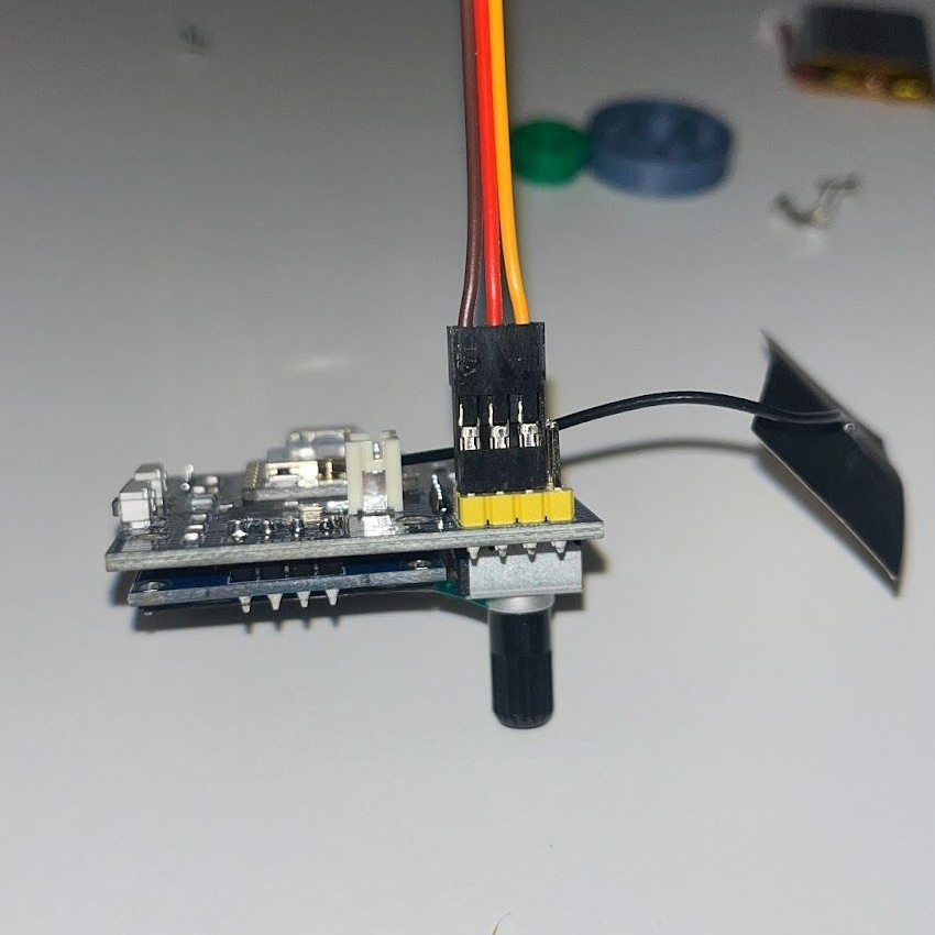
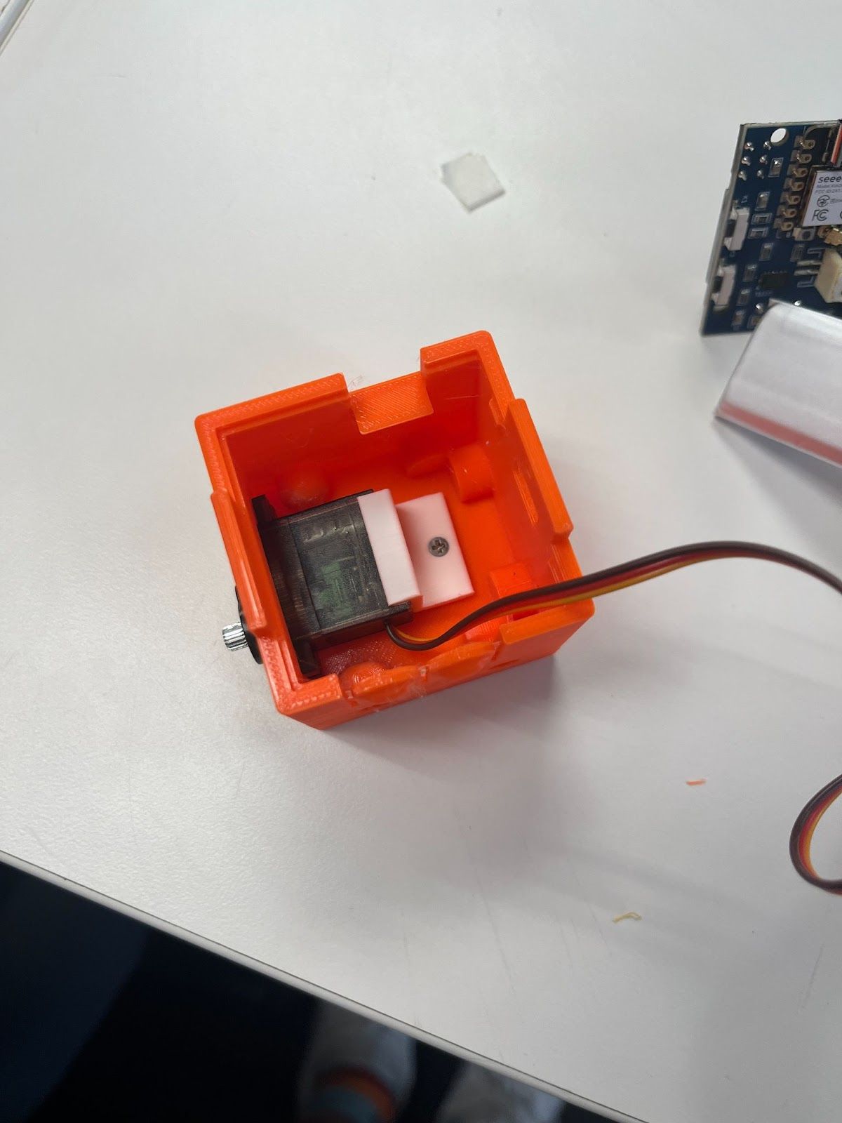
Connect the servo motor to the motor pins on the Smart Motor board.
- Ensure the wires are inserted in the row labeled "BATT" (if using battery)
- The brown wire should be on the inside
- There should be one unused header on the outside
- Attach the LiPo battery to the battery port on the Smart Motor board.
Step 2: Prepare the 3D Printed Parts
-
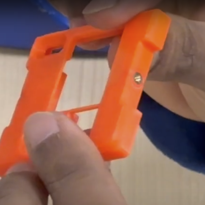
Insert the nut in the nut pocket (may not be required if your 3D prints have good tolerance):
- Place a 20mm bolt inside the bottom of the box
- Place the M2 nut and finger-tighten as much as possible
- Use a screwdriver to fully tighten the bolt until the nut is secure
- Remove the bolt when the nut is in place


-
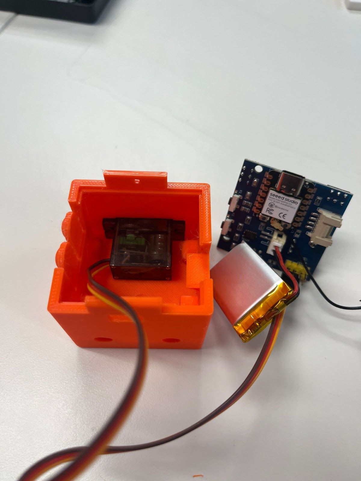
Insert the motor into the box.
-
Position the motor mount into the box and attach it with the 10mm bolt.
-
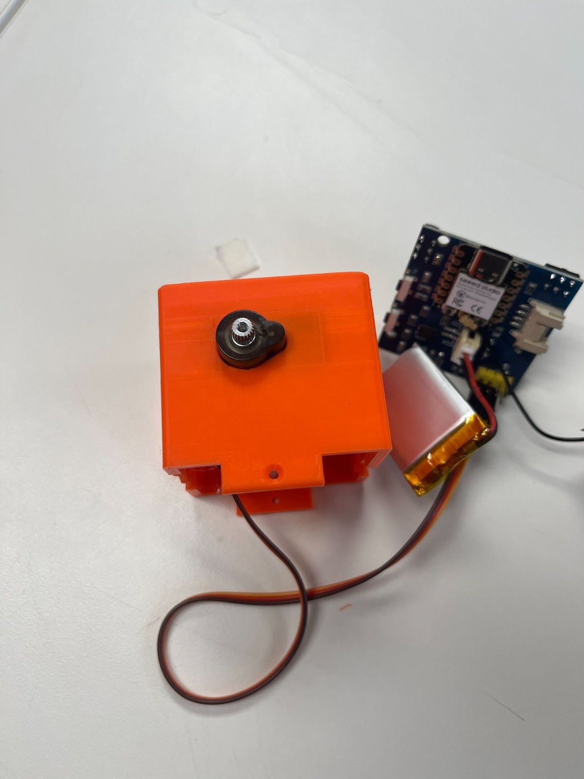
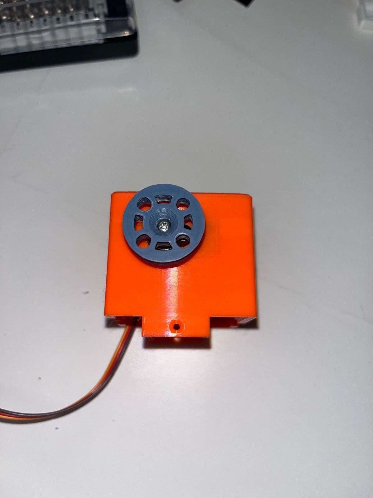
Attach the wheel to the servo motor:
- Push the wheel onto the outside arm of the motor
- The convex side should face toward the box and the concave side away
- This may require some force to attach
- Secure it with the bolt from the servo motor packet (not the screw)
Step 3: Final Assembly
-
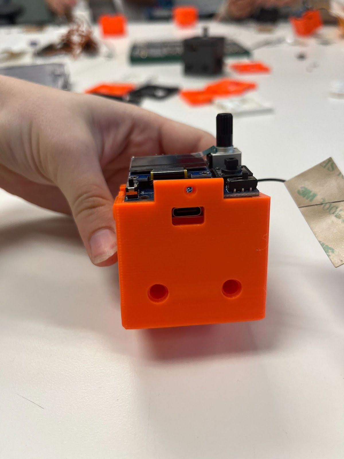
Insert the battery into the box.
-
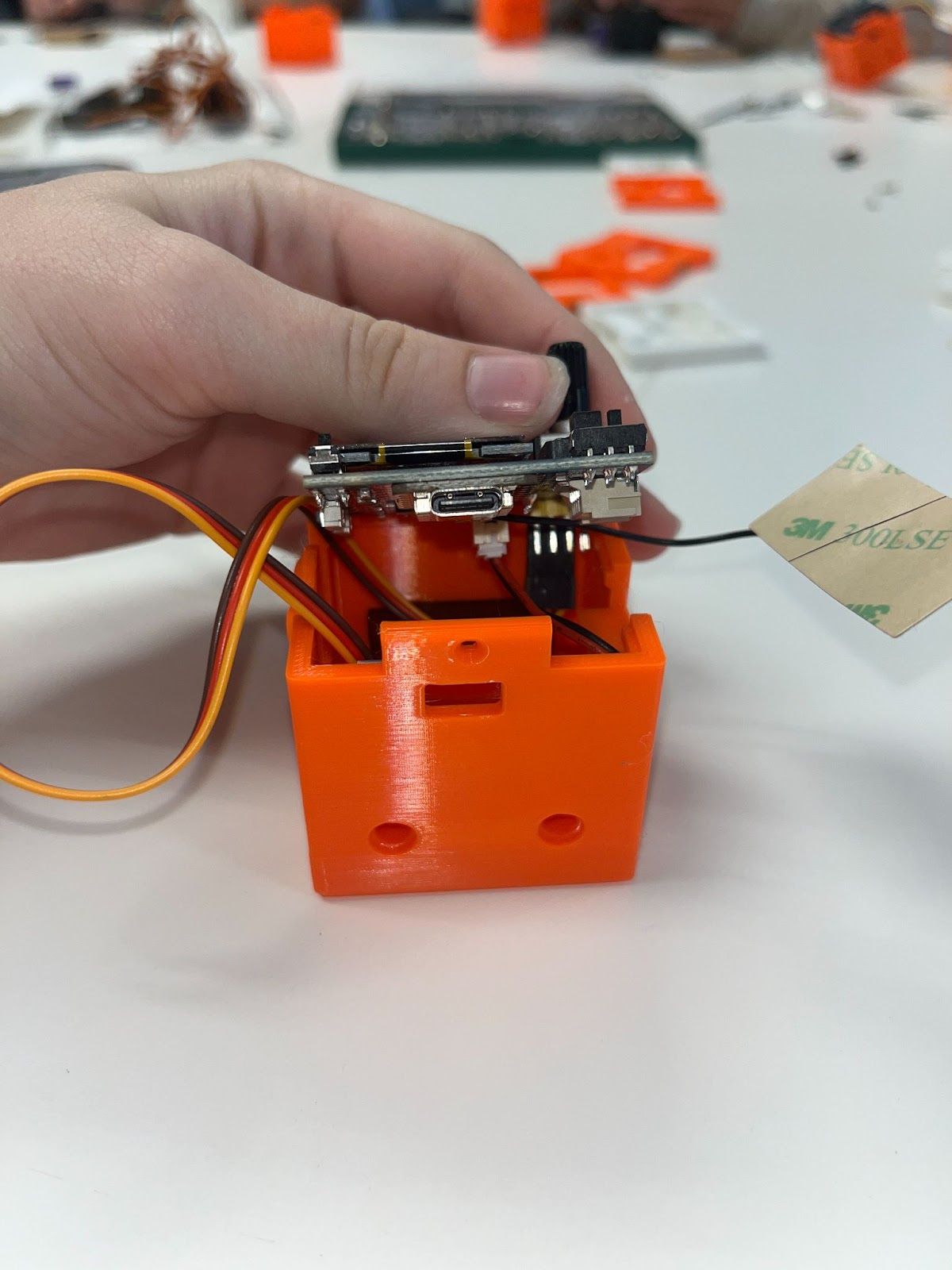
Arrange the electronics:
- Stuff the wire and antenna into the box
- Secure the Smart Motor board so it sits flush
-
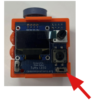
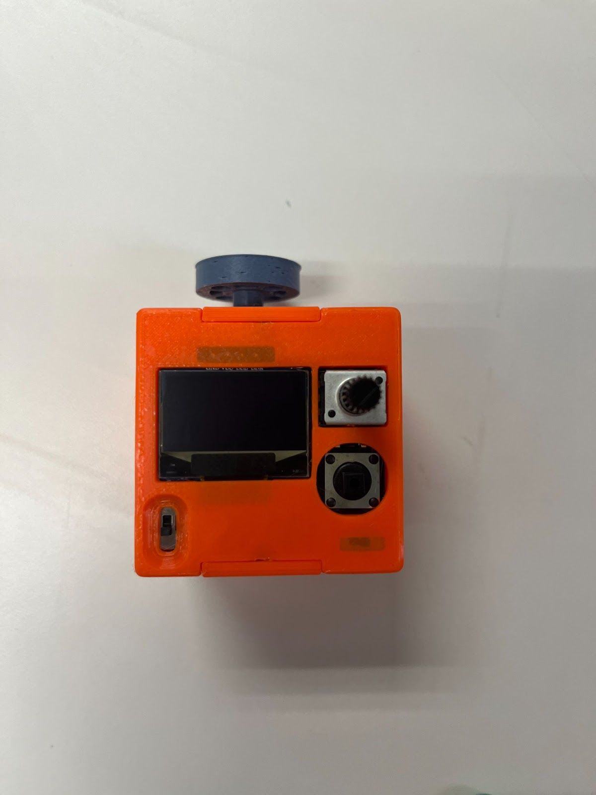
Set the sensor switch to analog by flipping the switch toward the right.
-
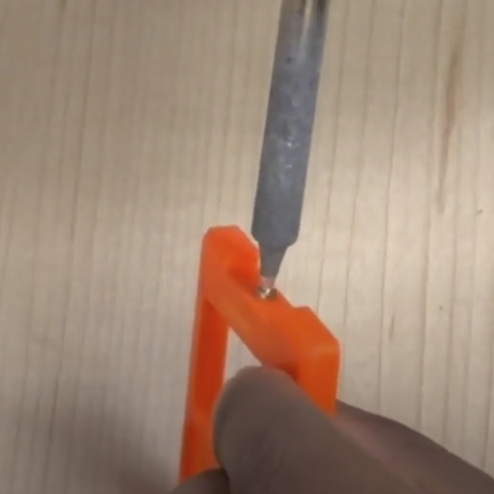
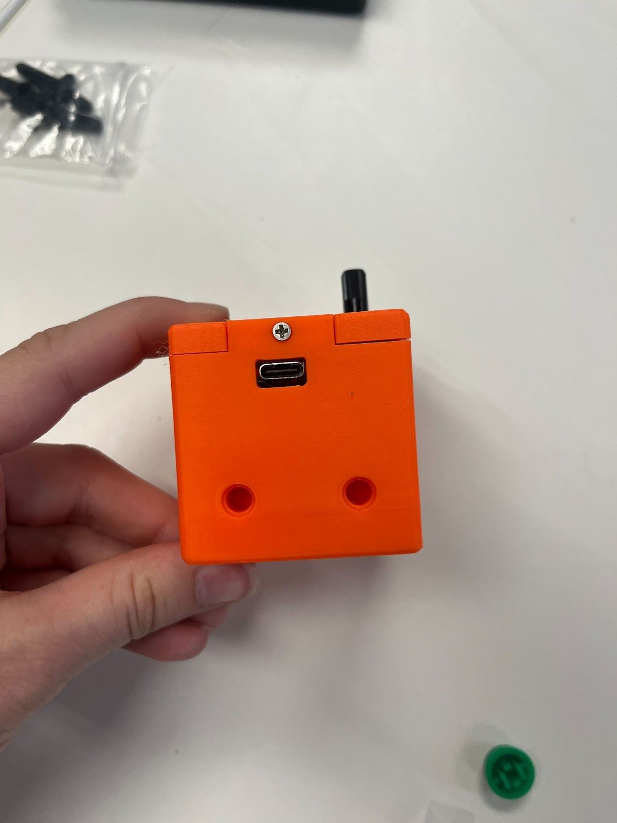
Install the threaded inserts:
- Use a soldering iron to insert the threaded inserts into the two holes on the TOP 3D printed part (watch video for demonstration)
-
Attach the top cover:
- Remove the protective film from the screen
- Place the TOP cover on the system
- Use the two 4mm screws to secure it in place
-
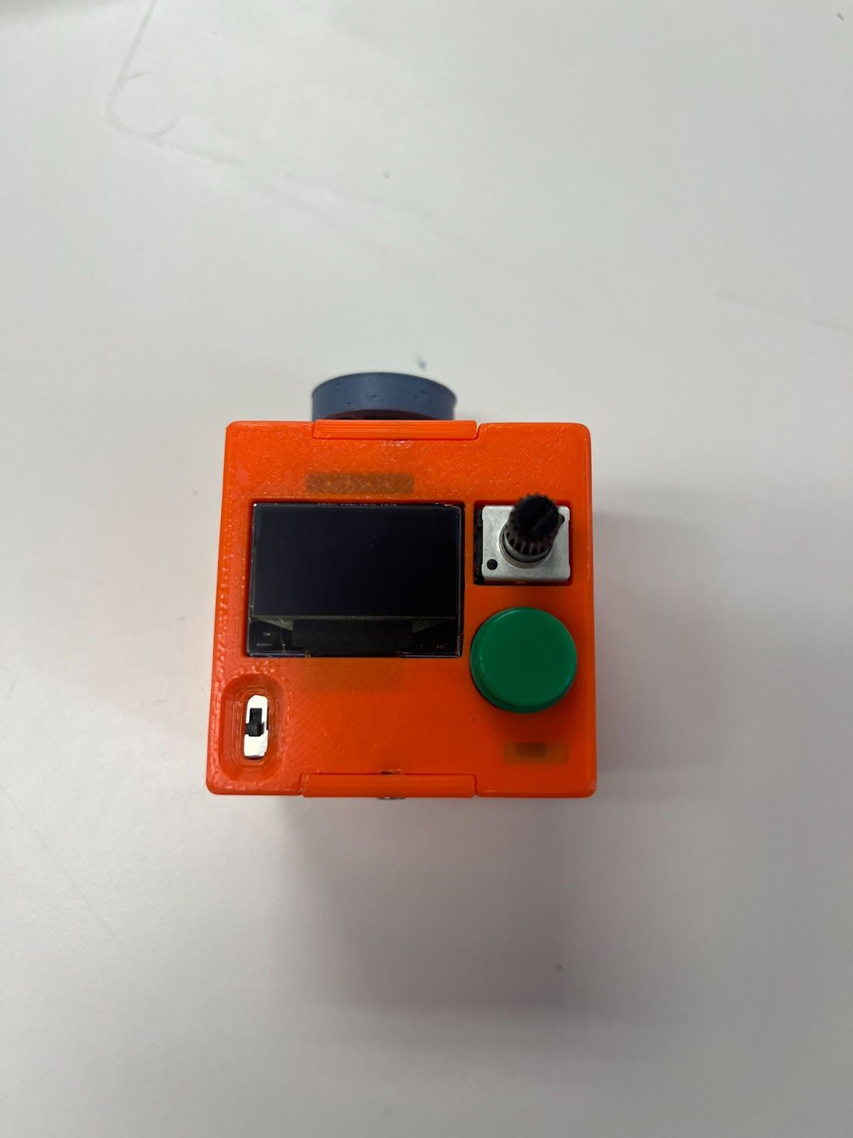
Install the button cover by pressing it into place.
Time Estimates
| Task | Estimated Time |
|---|---|
| 3D printing | 6 hours |
| Manual assembly | 3 minutes |
Programming Your Smart Motor
Use the Smart Motor Update Portal to flash micropython firmware and to upload the code on your Smart Motor.This guide is maintained by the Smart Motors team. For questions or support, please email us. Find our contact info in our Contact Us page.